Domestic Stormwater Drainage Systems
Stormwater disposal details, including plans and sections, must be identified on all Development Application submissions - usually on the site plan.
For domestic construction, including outbuildings such as garages, there are only three acceptable methods for the disposal of roof water and/or extensively paved areas. These are numbered below in preferential order.
1. Piped to the street
Where site gradients allow, all stormwater should be conveyed to the street gutter system via sealed pipes. Charged stormwater lines are not permitted.
Before you can connect your stormwater to the kerb and gutter, you'll need a permit from Council to excavate the footpath and road reserve. Use the form below to apply.
Application for Works in Road Reserve PDF, 1535.88 KB.
View fees for application for works on roads and footpaths.
2. Inter-allotment drainage
Where site gradients do not allow for street gutter disposal and an inter-allotment drainage easement is provided (ie all new residential subdivisions), all stormwater must be conveyed to the easement via sealed pipes with the provision of an overflow gully in the house line connection at a level lower than the lowest floor level.
3. Absorption disposal system
No further development will be permitted on the site where an absorption disposal system is proposed without a further stormwater management study demonstrating that the system is able to handle the additional runoff.
Where site gradients do not allow for street gutter disposal or disposal via an inter-allotment easement (ie older residential subdivisions), all roof stormwater must be conveyed to a 5000 L capacity rainwater tank (see State Environmental Planning Policy 4) so-as to restrict the flow of sediment to the absorption disposal system and retard flow.
The tank overflow must then be connected to an absorption disposal system. The area downstream must be grassed and vegetated in a manner that will ensure a reduction of subsurface flows into the adjoining properties. A rainwater tank may not be applicable for minor structures.
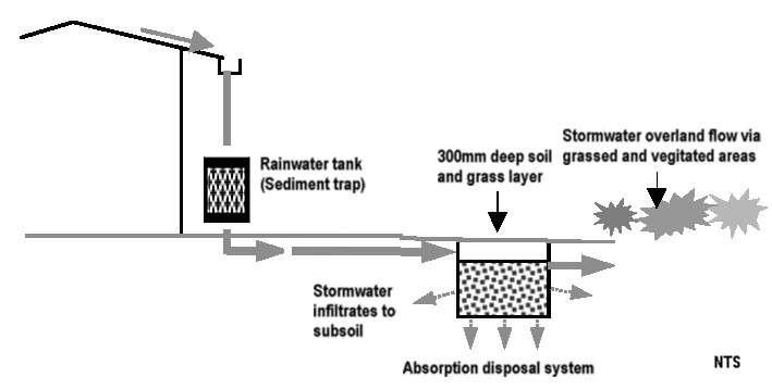
Detailed information about absorption trenches is shown below. You should seek the advice of a suitably qualified expert when designing or building an absorption disposal system.
Absorption disposal systems must not be used on land where the following conditions exist:
- Slope instability
- Loose sand
- Clay soils that collapse in contact with water
- Soils with a hydraulic conductivity of less than 0.36 mm/hr,
- Rock and shale
- Slopes greater than 15% (steep grades increase the chance of landslip and water seepage from the subgrade to the lower areas of the site reducing the amount of water infiltration)
- Extensively paved areas such as driveways.
As a guide, sand has a hydraulic conductivity of >180 mm/hr, sandy clay 180–36 mm/hr, medium clay 36–3.6 mm/hr, reactive clay 3.6‑0.036 mm/hr.
Council may permit absorption disposal systems in soils with a hydraulic conductivity of less than 0.36 mm/hr, slopes greater than 15%, or extensively paved areas.
In these cases, the design of the absorption disposal system must be prepared by a suitably qualified and experienced engineer. Details must be submitted with a development application and include an assessment of the infiltration of the soil profile, consideration of antecedent moisture conditions and performance over a variety of rainfall events.
The design must also be supported by a report from a practicing geotechnical engineer with local knowledge attesting to the suitability of the site for the system, absorption capacity of the system and demonstrate that there will be no adverse impacts on the subject land/buildings, adjoining and/or downstream properties by the re-direction or concentration of stormwater.
Absorption disposal systems may be one of two types as shown below. Location and details must be shown on plans submitted to Council with a development application.
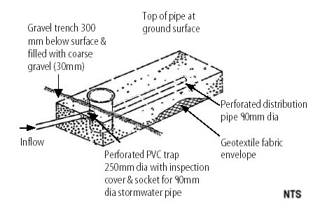
Absorption trenches
These must be fully lined with geotextile fabric, filled with 30 mm coarse gravel and topped with a 300 mm soil and grass layer for aesthetics that restrict the entry of silt to the system via a geotextile underlay.
The connection into the absorption trench from the rainwater tank must be via a 90 mm diameter inflow pipe passing through a 250 mm diameter covered PVC inspection trap to a 90 mm perforated distribution pipe allowing stormwater to percolate to the gravel. The base of the trench must not exceed a slope of 3%.
Infiltration cells
These are modular plastic systems that can be used in an absorption trench instead of gravel fill. As with absorption trenches, infiltration cells are surrounded with geotextile fabric and placed under a 300 mm layer of sand or loam. An infiltration cell generally has a greater volume of void space than a conventional gravel-filled retention trench; consequently it can provide a greater storage volume per unit of area.
These systems must be installed in accordance with the manufacturers’ recommendations, particularly in relation to the required volume which is dependent on site soil conditions.
Details must be submitted to Council with a development application. The connection into the infiltration cells from the rainwater tank must be via a 90 mm diameter distribution pipe allowing stormwater to fill the cells. The base of the trench must not exceed a slope of 3%.
Absorption disposal systems must be designed with sufficient capacity to store the inflow of a one in three months average recurrence interval design storm, with an emptying time of less than 24 hours.
As a guide in satisfying the above criteria for a roof catchment area of 150 m², an absorption disposal system being an absorption trench would require a volume of 6 m³ (depending on site soil conditions, see above). For each additional 25 m² of roof area or part thereof, 1 m³ of additional absorption trench must be provided.
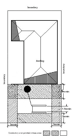
Absorption disposal systems must be sited across the gradient of the site and may be used in series i.e. 2 x 3 m³ if space becomes a problem (see diagram below).
The absorption disposal system is required to be located a minimum three (3) metres from the allotment boundaries and at least five (5) metres away from all buildings. The system must not be placed under any paved surfaces and must be at least one (1) metre away from pavements subject to vehicular traffic.
- Maps
- Property Information
-
Development and Planning Rules
- State and Regional Planning Policies
- Local Environmental Plans
- Development Control Plan
- Exempt and Complying Development
- Council's Development Policies
- Development Contributions
- Planning Proposals
- Development on Public Land
- Development on Bush Fire Prone Land
- Flooding, Stormwater and Development
- Development and Heritage Properties
- Caravan Parks, Camping Grounds and Manufactured Home Estates
- Development Advice
- Submit a Development Application
- View an Application
- Assessments and Determinations
- Activity Applications
- Building and Renovating
- Subdivision
- Housing
- Property Addressing
- Works on Roads and Footpaths
- Fire Safety
- Development Registers
- Community Land